
Effective earthing is one of those things you rarely notice when it's done right - and absolutely notice when it isn't. When a fault hits, the buried conductor system has to carry the current safely into the ground, hold touch and step voltages within safe limits for anyone on or near the site, and let the protection do its job. Everything about how well it does that is decided at design time, and most of it is decided by when in the design it happens.
Designed with the yard, not after it
An earth grid is not an independent system. Its geometry follows the yard: where the transformers sit, where the fence runs, where cable trenches cut through, where the gradient control needs to be densest because people stand there. When the earthing engineer works from the same layout as the engineer placing the plant, the grid and the yard are optimised together - conductor goes where the physics needs it, and the layout can shift while shifting is still cheap.
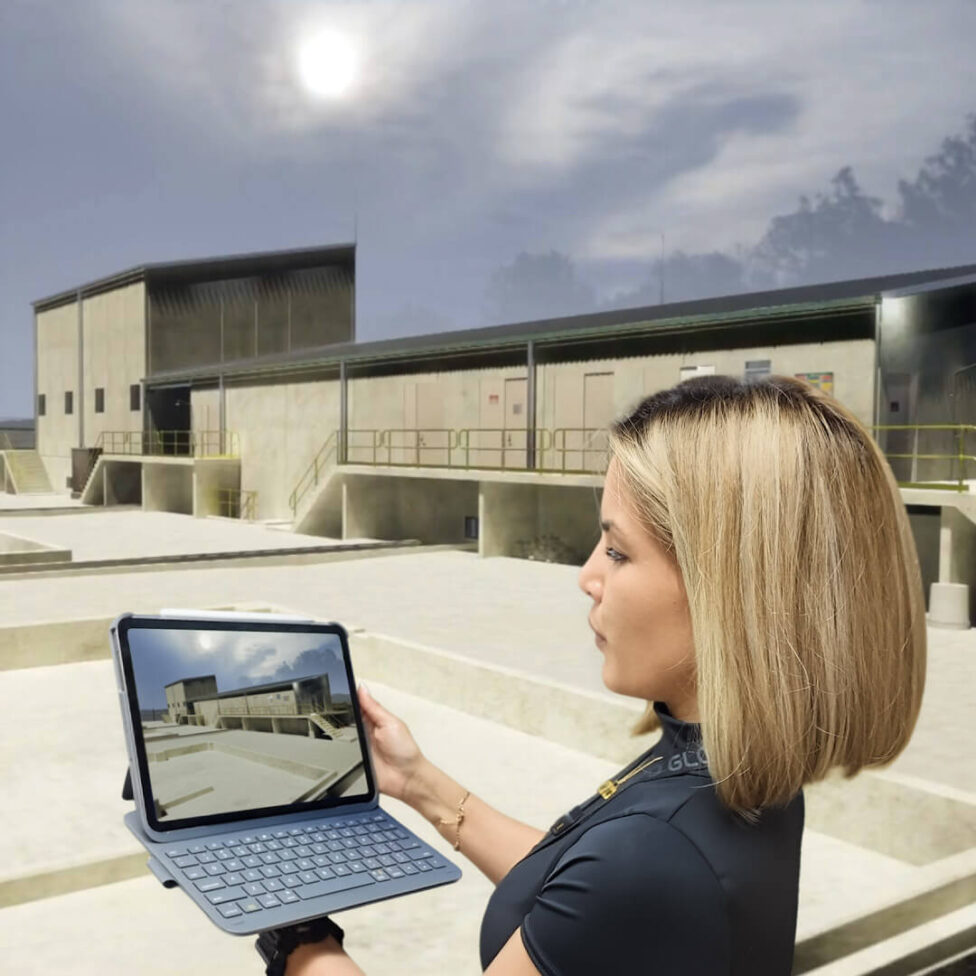
Retrofit the earthing after the layout is frozen and the sequence inverts. The grid must accommodate foundations already positioned, trenches already routed and a fence line already fixed. The design still has to meet the same standards - it just gets there with more conductor, more compromise and less margin. This is why APD Global keeps earthing inside the same bench as HV substation design, not with a subcontractor: every substation leaves with an earthing system designed and proven by the team that laid out the yard. At South Jerrabomberra, Essential Energy's greenfield 132 kV GIS zone substation, the earthing was designed inside the same multidisciplinary model as the building and the plant.
Model to measurement - the discipline that keeps it honest
Every APD earthing design follows the same sequence. It starts with on-site soil resistivity measurement - layered soil data from the actual site, not an assumed figure. That feeds a CDEGS model of the earthing system: grid impedance, earth potential rise, touch and step voltages, engineered against Australian and international standards. And it ends with current injection testing on the installed grid, with the system accepted only when the measurements agree with what the model predicted.
That last step is the discipline. A model that is never tested against the installed asset is a hypothesis. Model-to-measurement closes the loop: the design is proven by measurement, not assumption. Because sometimes, the best engineering outcome is that nothing happens.
EPR, LFI and the neighbours' assets
The consequences of an earthing fault do not stop at the fence. When fault current flows, the local ground rises in voltage - earth potential rise - and that voltage can transfer onto pipelines, fences and telecommunications assets nearby. Low-frequency induction puts voltage onto services running parallel to the corridor, with limits set to protect maintenance personnel on assets your project does not own.
These third-party assessments - EPR, LFI, EMF and transferred voltage onto pipelines - are integral to the earthing design, because they can drive the design: separation requirements, gradient control at boundaries, fence earthing arrangements. On constrained urban sites, such as the Perth CBD zone substations APD has delivered earthing design and testing for, transferred voltages onto the surrounding infrastructure are frequently the governing case, not conditions inside the yard. An earthing design that only considers the site itself has answered half the question.
BESS sites - new plant, same physics, harder geometry
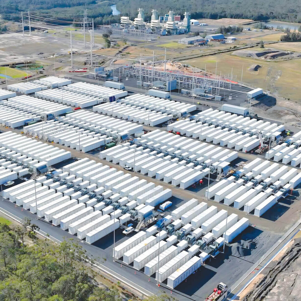
Battery energy storage sites concentrate the awkward parts of the earthing problem: large fault levels, extensive buried cable networks tying together many inverter and battery units, public boundaries, and network operator requirements that must be satisfied before connection. Inverter fault behaviour differs from synchronous plant, and the earthing study has to prove the combined system - the BESS yard, its substation and the surrounding services - keeps touch and step voltages within limits.
APD's earthing work on battery projects runs from community-scale storage, such as the Alkimos community battery, through to grid-scale BESS - design, EPR assessment and post-installation testing delivered as part of the same connection scope as the BESS and grid connection engineering. The same model-to-measurement discipline applies at every scale: the site is tested after installation, and accepted when measurement matches prediction.
The integration argument
None of this is exotic. Soil resistivity, CDEGS, EPR, injection testing - the methods are standard. What separates earthing that simply works from earthing that becomes a late-stage problem is integration: the grid designed with the layout rather than after it, the third-party assessments run alongside the site design, and the installed system verified against the model before anyone relies on it.
That is a structural choice about how the design team is built. Earthing at APD Global sits with the same bench that does the substation design itself - one model, one layout, one team - with earthing design and testing carried from soil test to injection test. When a fault hits, the site responds exactly as designed. That is the whole point.