
Substation earthing design is the engineering of the buried conductor grid that carries earth fault current safely into the ground - keeping touch and step voltages tolerable for anyone on or near the site, protecting plant, and letting protection operate correctly. In Australia it is argued under the ENA's risk-based EG-0 framework and IEEE 80's deterministic limits, installed to AS 2067, and proven by injection testing. Everything below is how that argument gets built.
1. The standards: who governs what
What is the IEEE standard for earthing systems?
IEEE 80 - the IEEE Guide for Safety in AC Substation Grounding, current edition IEEE 80-2013. It defines the tolerable touch and step voltage limits, soil modelling and earth-grid design methodology used worldwide, and Australian network owners cite it in their own earthing standards alongside AS 2067 and the ENA's EG-0 and EG-1 guides. IEEE SA →
What is IEEE 80?
IEEE 80 is the deterministic design method for substation earth grids. It derives a tolerable body current from fault clearing time and body weight, converts that into touch and step voltage limits - adjusted for the surface layer underfoot, which is why switchyards are covered in crushed rock - and provides the methodology to design a buried grid that keeps a worst-case fault inside those limits.
Deterministic means exactly that: assume the worst credible fault, at the worst location, with a person standing at the worst point on the site, and design so even that case is survivable. It is a conservative, auditable argument, and it remains the calculation machinery behind most Australian earthing studies. One status note worth knowing: IEEE SA has listed IEEE 80-2013 as Inactive-Reserved since March 2024, but it remains the cited edition across Australian utility standards and the industry-standard guide in practice.
What is EG-0 - and what makes it different?
EG-0 is the Power System Earthing Guide, Part 1: Management Principles - ENA DOC 025-2022, published by Energy Networks Australia and first issued in 2010. It is Australia's risk-based earthing framework: instead of designing every site to a single worst case, it quantifies the probability that an earth fault and a human contact actually coincide, and manages the resulting fatality risk to societally tolerable levels. ENA guidelines list →
The probabilistic argument changes what a compliant design looks like. A fault lasting half a second and a hand on a fence have to happen in the same half-second for anyone to be at risk - so EG-0 weighs fault frequency, contact frequency and duration, and the probability that the resulting body current causes fibrillation. The computed individual risk is then placed against tolerability bands: broadly, risk below one in a million per year is acceptable, above one in ten thousand is intolerable, and the region between is managed down as low as reasonably achievable - the ALARA band, where mitigation is argued on cost against risk reduction. A remote terminal station with rare faults and rarer visitors can justify a very different grid from a metro zone substation with a bus stop against the fence - that is the point.
Under EG-0 sits EG-1, the Substation Earthing Guide - ENA DOC 045-2022 - the application guide that turns the framework into substation-specific design, installation, testing and maintenance practice. A common confusion worth clearing up: the old ESAA EG-1 of 1998/2000 was withdrawn years ago, and some references still describe EG-1 as dead. It is not - Energy Networks Australia re-issued it in 2022, and current utility standards cite the 2022 edition.
Probabilistic or deterministic - which applies in Australia?
Both, usually together. EG-0 is the Australian framework - most network owners anchor their earthing standards to it - while IEEE 80 supplies the body-current science and grid design methodology inside the calculation. The utilities' own documents say so explicitly: Energex and Ergon's STNW3028 names EG-0, EG-1 and IEEE 80 together; Western Power's earthing standard pairs AS 2067 with EG-0. The practical rule: the risk argument runs under EG-0, the numbers inside it come largely from IEEE 80, and the network owner's standard decides the dialect. Which owner weights which document how is mapped in our substation standards reference.
Where AS 2067 fits
AS 2067 - Substations and high voltage installations exceeding 1 kV a.c. - is the installation standard over the top of both. It requires a risk-based earthing approach consistent with EG-0's philosophy and sets the installation requirements the yard is inspected against: bonding of structures and screens, fence earthing, separation and the interface with LV earthing systems. The design method comes from EG-0, EG-1 and IEEE 80; the installed result has to satisfy AS 2067. Standards Australia →
Every standard, every owner
AS 2067, the ENA guides and all thirteen network owners' earthing dialects - mapped layer by layer in the standards reference.
Open the reference →2. The workflow: soil test to injection test
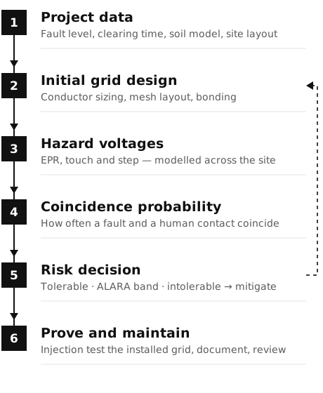
Every substation earthing design, under either philosophy, moves through the same five steps. The standards decide how the acceptance criteria are argued; the workflow is common - and the discipline that holds it together is that the model built at step three is the same model the site is tested against at step five.
Step 1 - How is soil resistivity measured? The Wenner method
Soil resistivity is measured on site with the Wenner four-electrode method: four equally spaced electrodes are driven in a line, current is injected through the outer pair and voltage measured across the inner pair, giving resistivity ρ = 2πaR. Repeating the traverse at wider spacings reads progressively deeper soil, building the layered model the whole design stands on.
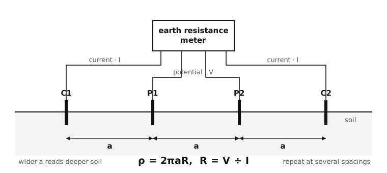
Why it matters this early: resistivity in Australia spans orders of magnitude - coastal clays measure tens of ohm-metres, dry granite country tens of thousands - and a two-layer soil where a conductive band sits under a resistive cap behaves nothing like the uniform soil a textbook assumes. An earthing design built on an assumed resistivity figure is a guess wearing a report cover. Measured, layered soil data from the actual site is the first deliverable of a real design, and it is also the input the geotechnical and foundation designers want measured anyway.
Step 2 - How much fault current actually enters the grid?
Not all of the fault current the short-circuit study predicts flows through the earth grid into the soil. A substantial share returns to source through metallic paths - overhead earthwires on the transmission lines, cable sheaths and screens - and the local transformer's contribution circulates without entering the ground at all. The fraction that does flow through the grid is the grid current, and getting it right is the difference between a realistic design and an over-built one.
This is why the earthing study and the fault level study must share one data set. The split between soil and metallic return paths changes with every line rebuilt and every cable laid, and a grid designed for yesterday's fault current answers a question the network is no longer asking. On connection projects, the earthing interface assessment belongs inside the same study package as the short-circuit work - the grid connection guide covers where it sits in the sequence.
Step 3 - Grid modelling: touch and step voltages
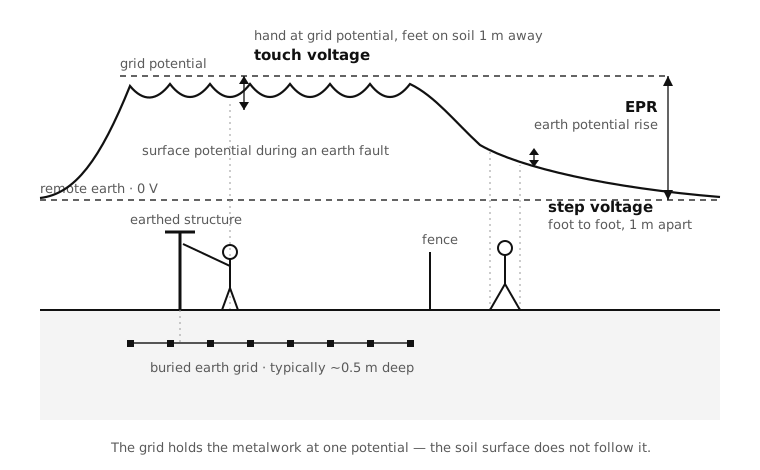
With the soil model and grid current fixed, the buried grid is modelled - in practice in CDEGS, the industry-standard suite - to predict grid impedance, earth potential rise, and the touch and step voltages appearing across the site. The layout follows the yard: conductor densest where people stand, gradient control at gates and fences, bonding for every structure, screen and pipe entering the site.
The same model answers the questions beyond the fence. Earth potential rise does not stop at the site boundary: it transfers onto pipelines, fences and telecommunications assets, and low-frequency induction loads services running parallel to the corridor. On constrained urban sites those third-party effects - not conditions inside the yard - are frequently the governing case, which is why the EPR, LFI and transferred-voltage assessments run inside the earthing design, not after it. Why earthing can't be an afterthought →
Step 4 - What voltage is tolerable? The criteria
Here the two philosophies diverge. IEEE 80 computes fixed limits: a tolerable body current from clearing time and body weight, converted into touch and step voltage limits credited with the surface-layer resistance underfoot - one pair of numbers, every exposed location designed inside them. EG-0 computes a risk: the same hazard voltages weighed by the probability of coincidence, producing site-specific criteria that can be tighter than IEEE 80 where exposure is high and looser where it is genuinely negligible.
In practice the Australian argument is layered. The network owner's standard nominates the method - most anchor to EG-0's risk-based criteria with IEEE 80's machinery inside, several accept either, all expect the choice to be stated and defended. The deliverable the reviewer wants is the same under both: every touch and step scenario on and around the site identified, the criterion applied to each, and the margin shown. An earthing report written in the wrong network's dialect reads as wrong even when the grid is right.
Step 5 - Commissioning: the injection test that proves it
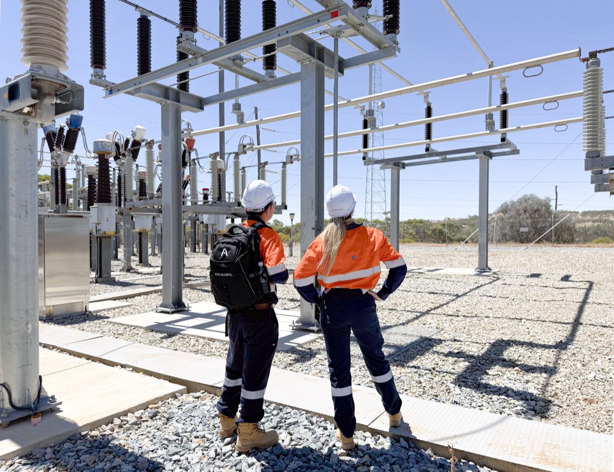
A model that is never tested against the installed asset is a hypothesis. Current injection testing closes the loop: the installed grid is energised at a known current - injected from a remote electrode, typically via a de-energised line or a dedicated test circuit - and the actual earth potential rise, grid impedance and the voltages appearing on structures, fences and neighbouring assets are measured and compared against what the model predicted. The system is accepted when measurement agrees with prediction, and not before.
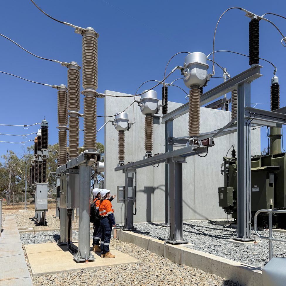
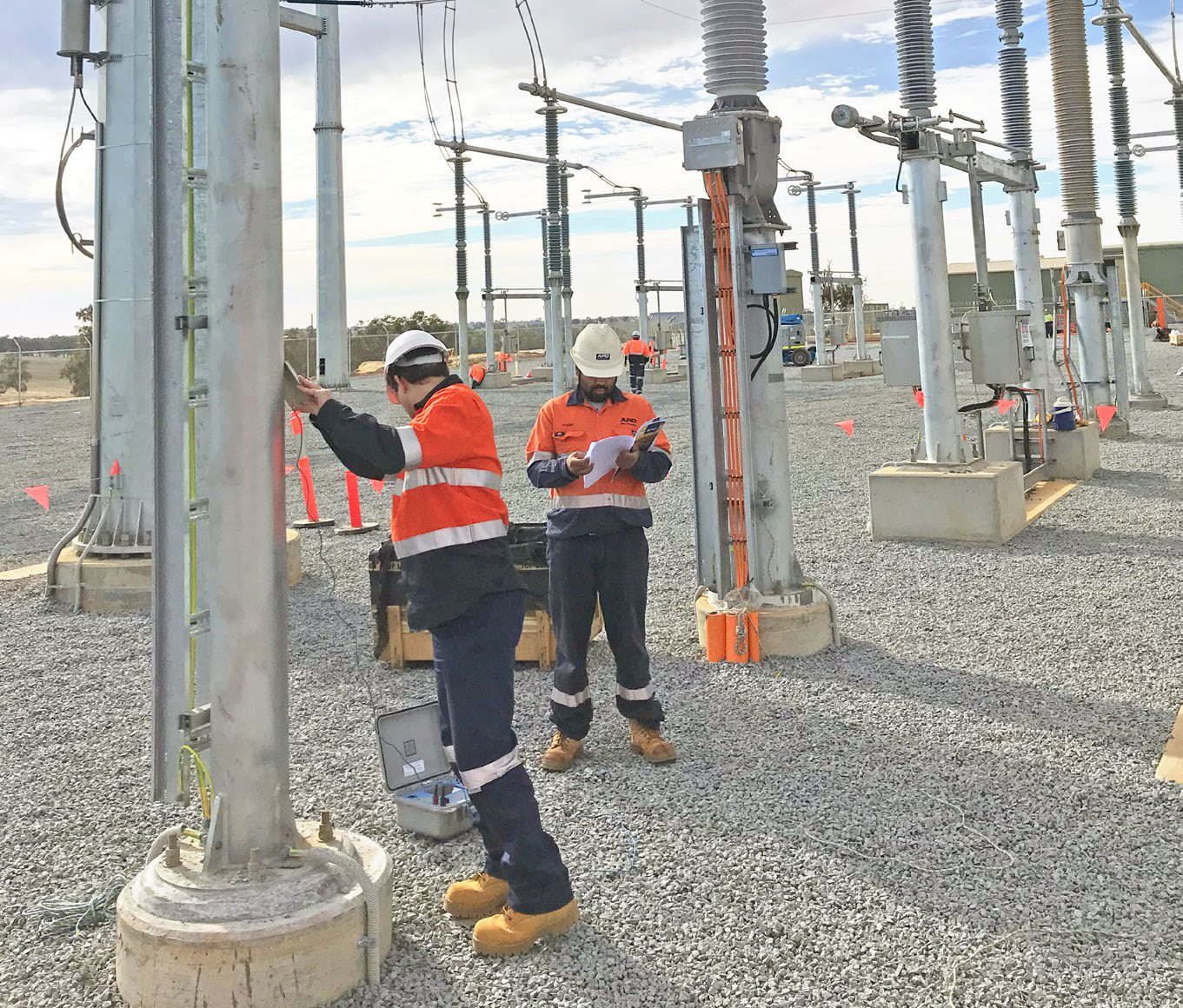
APD performed exactly this at the Yandin Wind Farm's 330/33 kV substation - the earth grid designed with the yard, then proven by current injection before the site relied on it. The test is not ceremony: it catches the things models cannot see, from an unbonded screen to a soil layer the traverse missed, while they are still cheap to fix.

The method, on real sites
Model to measurement, at every scale.
Yandin Wind Farm
Earth-grid current injection testing at the 330/33 kV substation - the installed grid measured against the design model before the site relied on it.
The earthing service →Perth CBD zone substations
Earthing design and testing on constrained urban sites - where transferred voltages onto the surrounding infrastructure, not conditions in the yard, govern the design.
The integration case →Jerrabomberra Zone Substation
Greenfield GIS zone substation for Essential Energy - earthing designed inside the same multidisciplinary model as the building and plant, never retrofitted.
The project →Frequently asked questions
What is proper earthing?
Proper earthing is a system designed, installed and proven to carry the worst credible fault current into the ground while keeping touch and step voltages tolerable for anyone on or near the site. In Australian substation practice that means a design argued under EG-0 and IEEE 80, installed to AS 2067, and verified by current injection testing after installation.
How to calculate earthing size?
Earthing conductors are sized thermally, using the adiabatic equation: the cross-section must carry the prospective fault current for the full clearing time without exceeding the conductor's temperature limit. In LV installations, AS/NZS 3000 Table 5.1 does this by lookup against the active conductor size. In HV substations the fault current and clearing time are calculated and the grid conductor sized directly - commonly 70–120 mm² copper, with allowance for corrosion and future fault level growth.
What is the minimum size for a main earth conductor?
Under AS/NZS 3000, a copper main earthing conductor must be at least 4 mm², sized from Table 5.1 against the largest active conductor of the consumer mains, and need not exceed 120 mm². HV substation earth grids are sized differently - thermally, against the site's fault current and clearing time - and typically use 70 mm² copper or larger. AS/NZS 3000 →
Can we use 2.5 mm wire for earthing?
Only for LV protective earthing of smaller circuits: AS/NZS 3000 Table 5.1 permits a 2.5 mm² copper earthing conductor for copper active conductors up to 6 mm². It is never acceptable as a main earthing conductor, which must be at least 4 mm², and it has no place in an HV earth grid, where thermal sizing against fault current governs.
What section is earthing in AS3000?
Section 5 - Earthing Arrangements and Earthing Conductors. It covers the MEN system, main earthing conductors, protective earthing, equipotential bonding and earth electrodes for LV installations. HV substation earthing sits largely outside AS/NZS 3000: it is governed by AS 2067, with the design methodology drawn from the ENA's EG-0 and EG-1 guides and IEEE 80.
How many earthing is required for DG?
Australian practice does not prescribe a fixed count of earth electrodes for a generating set. Under AS/NZS 3000 and AS/NZS 3010, the set is earthed through the installation's earthing system - the MEN arrangement - with the neutral and frame earthing determined by the installation's configuration, not by a quota of rods. The familiar rule of two electrodes for the neutral and two for the body comes from overseas codes and is not an Australian requirement.
Talk to the team that proves its grids
APD Global delivers earthing design and testing across Australia and New Zealand - soil resistivity to CDEGS model to injection test, inside the same team that does the substation design itself. The standards landscape the design must satisfy, owner by owner, lives in the substation standards reference.