
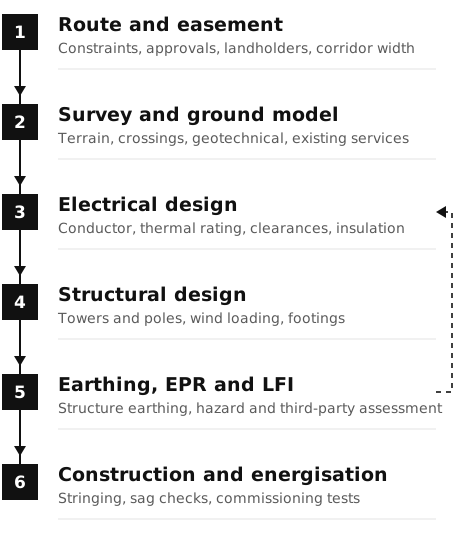
Transmission line design is the engineering of high-voltage overhead lines and underground cables - route selection, conductor and insulation choice, structure and foundation design, clearances and earthing - so the line carries its rated power safely for decades. In Australia it is governed by AS/NZS 7000 and each network operator's standards, such as Western Power's or Transgrid's. Everything below is how that design gets built, in the order it gets built.
1. The standards: AS/NZS 7000 and the owner's dialect
What standard covers overhead line design in Australia?
AS/NZS 7000 - Overhead line design - is the governing standard for transmission and distribution overhead lines in Australia and New Zealand. It sets the limit-state design basis: electrical clearances, mechanical loading, structure and foundation strength, and service life. Each network operator layers its own standards and standard designs over it - Western Power, Transgrid and Transpower all publish their own suites. Standards Australia →
Limit-state means the line is designed the way bridges are: every load case - wind, conductor tension, construction and maintenance loads, failure containment - is factored and checked against the factored strength of every component, from conductor fitting to footing. That is a different discipline from the working-stress methods older lines were built to, and it matters most on brownfield work, where a new design meets fifty-year-old assumptions mid-span.
The owner's dialect sits over the top. Western Power publishes standard designs for its transmission lines; Transgrid, Powerlink and the other TNSPs maintain their own specifications, conductor schedules and approved structure families; Transpower runs the same model across New Zealand. A line designed to bare AS/NZS 7000 without the owner's suite reads as wrong to the reviewer who has to accept it - which is why panel appointments with Transgrid, Western Power and Transpower are the working context of this discipline, not a credential.
2. Route selection and easements
How are transmission line routes selected?
By constraint mapping before any engineering: terrain and geotechnical conditions, land tenure and easement acquisition, environmental and heritage approvals, bushfire risk, crossings of roads, rail, rivers and existing services, and access for construction and maintenance. Candidate corridors are scored against cost and risk, then the preferred route is walked, surveyed and refined span by span.
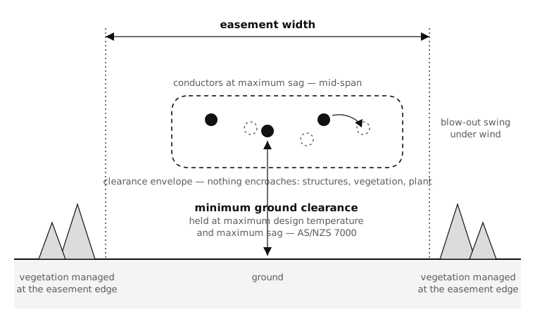
The route decision is the most expensive decision on the project, made with the least information - every kilometre of corridor commits easement acquisition, structure count, access roads and decades of maintenance. The easement itself is part of the design: wide enough for conductor blow-out and vegetation clearance at the line's hottest, windiest case, with its width set by the clearance work in section 3, not by convention. Get the route wrong and no amount of tower optimisation buys it back.
Transmission line design
Overhead line and cable design, 330 and 500 kV tower design, stringing systems and REZ studies - Transgrid, Western Power and Transpower panels.
The transmission service →3. Electrical design: conductor, rating, clearances
Which conductor is used for a 220 kV transmission line?
Typically a stranded aluminium conductor - ACSR (aluminium conductor, steel reinforced) or AAAC (all-aluminium alloy conductor) - often bundled as twin conductors per phase. The exact selection is an optimisation: current rating and losses against sag, tension and structure loads, with the network operator's standard conductor schedule usually settling the final choice.
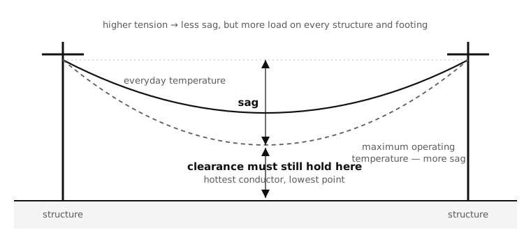
Conductor selection drives everything downstream. A heavier conductor carries more current but loads every structure and footing on the line; a hotter-running conductor carries more current through the same steel but sags further, and sag is where the electrical design meets the ground. The thermal rating case - maximum design temperature, worst ambient, full load - sets the lowest the conductor will ever hang, and that governs structure heights across the whole route.
Clearances: the envelope nothing may enter
AS/NZS 7000 prescribes the clearances the line must hold - to ground, to roads and rail, to buildings, to other circuits and to the vegetation at the easement edge - at maximum sag and maximum conductor swing, not on a mild day. The design works backwards from that envelope: span lengths, structure heights and conductor tensions are chosen so the worst combination of temperature and wind still clears everything beneath and beside the line. Undercrossing protection - the engineering that lets a new line cross an existing one safely - is part of the same clearance discipline.
Insulation, lightning and the earthwire
Insulation coordination sets the insulator strings and air gaps for the voltages the line will actually see - power frequency, switching surges and lightning - against the pollution and altitude of the route. Overhead earthwires shield the phase conductors from direct strikes and carry fault current home, with OPGW doing double duty as the communications path; and every structure is earthed so a lightning strike or insulator flashover finds a controlled path to ground rather than a back-flashover across the string. Structure footing resistance is not a construction afterthought - it is a design parameter, checked where the lightning performance needs it.
4. Structural design: towers, poles and footings
The structural task is defined by AS/NZS 7000's loading provisions: regional wind converted into pressure on every conductor, every panel of lattice and every insulator string, combined with conductor tensions - intact and broken-wire - construction loads and maintenance loads, all factored and checked limit-state. Structure family follows the duty: lattice suspension towers for the long straight runs, strain and terminal towers where the line turns or ends, steel and concrete poles where footprint or amenity rules out lattice.
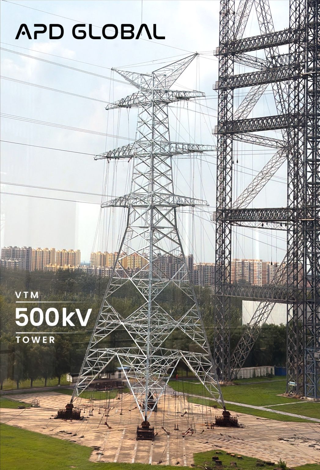
Design confidence has a hierarchy. Software proves the member forces; full-scale testing proves the structure. On HumeLink West, APD's alpine VTM strain towers - 74.2 metres tall, 150 tonnes - went through full-scale load testing, and on CopperString the 500 kV suspension tower D5S2BI and light tension tower D5T15BI were designed for the line joining Mount Isa to the National Electricity Market. A tower that has been tested to its design events is a different class of confidence from one that has only ever lived in software.
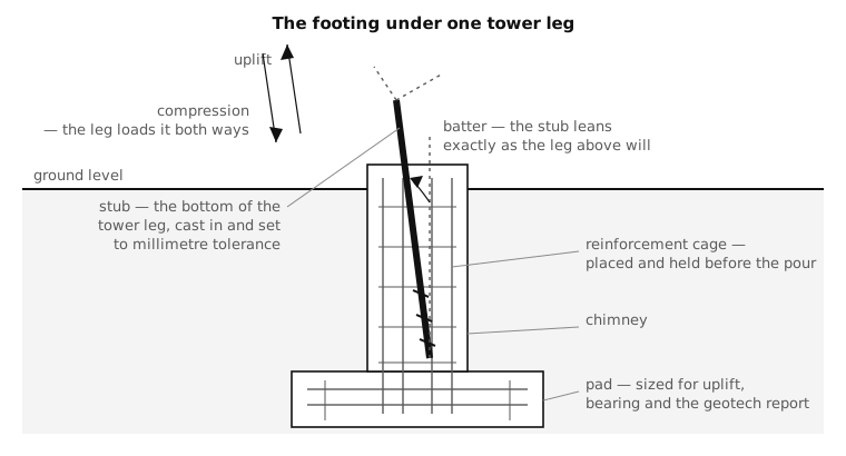
Below ground, the footing carries all of it - uplift on one leg, compression on another, shear through all four, in whatever the route's geology offers. Foundation design spans steep terrain, flood-prone corridors, reactive soils and mining subsidence areas, and it starts from measured geotechnical data, not assumed. The same ground investigation feeds the foundation design in the next section - and the earthing design after it.
5. Towers, foundations and civil works
A transmission tower is a civil and structural engineering job as much as an electrical one. Every member in a lattice tower - leg, bracing, redundant - is individually designed and checked, in practice in PLS-TOWER, against every factored load case the structure will ever see, then detailed for fabrication: bolted connections, splice positions, galvanised angle steel, an erection sequence a crew can actually build. Lattice wins on steel efficiency and logistics - it travels as bundled angle sections and goes together bolt by bolt in country no crane pad will ever reach easily; monopoles win on footprint and visual profile, and pay for it in plate steel, foundation moment and crane time. The choice between them is engineering, not aesthetics.
What foundations do transmission towers use?
Bored concrete piers and pad-and-chimney footings are the workhorses - one under each leg of a lattice tower. Steel grillages suit remote sites where concrete is hard to deliver, screw piles suit soft ground and fast programs, and rock anchors take the uplift where sound rock sits near the surface. The route's geology decides, footing by footing.
Each footing is a reinforced-concrete structure in its own right. The excavation is opened, and the reinforcement cage - the steel skeleton the concrete works through - is fabricated, placed and held to its cover tolerances before the pour; in a bored pier the cage goes down the shaft, in a pad-and-chimney footing it ties the pad into the column above it. The quiet precision discipline is stub setting. The stub - the bottom panel of each tower leg - is cast into the concrete, and the four stubs under a lattice tower must hold position, level and batter to millimetres relative to each other, because the steelwork above is fabricated to tight tolerance and does not forgive a footing poured in the wrong place. Setting templates, survey control and independent checks before and after the pour are what let fifty metres of bolted steel stand plumb on four buried points.
How are transmission towers tested?
At full scale. A prototype is erected on a dedicated test bed and the design load cases - wind, broken-wire, construction - are applied through rigging at calibrated load points, held at 100 and often 110 per cent of ultimate design load, with many campaigns finishing in a test to destruction to find the true failure point.
Full-scale testing is where the analysis model stops being a claim. The campaign loads the prototype case by case, increment by increment, deflections surveyed at every hold - and a destruction test at the end goes past design on purpose, to find the member that actually governs and the real margin behind the factored one. It is the verification AS/NZS 7000's design philosophy leans on for new structure families, and it closes the loop that started at the member sizes. APD's team runs this discipline end to end on major programs: on HumeLink West, the 500 kV VTM strain tower went from first outline through detailing and proto-assembly inspection to full-scale load testing - passed at 110 per cent. That campaign →
That discipline now has its next program. APD has been awarded the design of a new family of high-capacity 330 kV quad-conductor transmission towers for Western Power’s network in Western Australia - every member designed in-house, then proven through a full-scale prototype test campaign: load cases held at 100 and 110 per cent of ultimate design load, finishing in a test to destruction to establish the true failure modes. Tower families are generational infrastructure - the designs that pass that test bed will carry Western Australia’s power for decades.
APD has been awarded the development of a new family of high-capacity 330 kV quad-conductor transmission towers for Western Power's network in Western Australia. Every structural member is designed in-house, and the program follows the same full verification path: load cases applied through rigging at calibrated load points, held at 100 and 110 per cent of ultimate design load, then tested to destruction to establish true failure modes and confirm the design has the margins the analysis predicted. Tower families designed and verified this way are expected to serve the WA network for decades.
6. EPR, LFI and the earthing interface
When an earth fault lands on a transmission line, the current that enters the ground raises the local earth potential - EPR - at the structure, and the current flowing in the line induces voltage into anything metallic running parallel to the corridor: pipelines, railways, telecommunications cables. That second effect is low-frequency induction, LFI, and on long lines sharing a corridor with third-party assets it is frequently the governing hazard case, not conditions at the structures themselves.
The assessment runs inside the line design, not after it: structure earthing and footing resistance, EPR at each structure and at the terminal substations, LFI and transferred voltage onto neighbouring assets, EMF where the easement passes occupied land, and lightning performance - modelled in CDEGS and argued under the same ENA framework that governs substation earthing. How that framework works, risk-based EG-0 against deterministic IEEE 80, is its own guide: the substation earthing design guide. The service behind it is earthing design and testing.
7. Environment, bushfire and the corridor
Environmental and heritage approvals shape the route as hard as terrain does - threatened species habitat, cultural heritage, visual amenity and agricultural land use all move structures and bend corridors, and the approvals program frequently sets the project schedule. The design responds span by span: longer spans over sensitive ground, structure placement that follows farm boundaries, access tracks routed to the approval, not the shortest line.
In Australia, bushfire runs both directions. The line must survive fire weather - conductor clashing in extreme wind is a known ignition mechanism, and clearance-to-vegetation at the easement edge is the control that mitigation programs audit hardest. And fire changes the corridor itself: smoke and flame under a line can flash the air gap, which is why fire-season operation and easement vegetation management are designed in, not left to the maintainer to discover.
8. Brownfield: upgrades and reconductoring
A growing share of transmission design is not new corridor at all - it is more capacity through existing easements. Reconductoring swaps the conductor for one that runs hotter or carries more current within the same structure loads; thermal uprating re-argues the existing conductor's rating against measured, rather than assumed, conditions; and structure-by-structure assessment finds the spans where a fifty-year-old line and a modern limit-state check disagree. The discipline is the same as greenfield design run in reverse: the clearances and loads are fixed by what exists, and the engineering finds what fits inside them - on a line that usually has to stay energised while the work is planned around outage windows.
9. Overhead or underground
The corridor decision is engineering economics. Overhead is typically several times cheaper per kilometre at transmission voltages, faster to build and simpler to repair; underground wins where easements cannot be acquired, where visual amenity or bushfire exposure rules overhead out, or where the corridor crosses ground nothing may be built over. Cables bring their own physics - charging current that limits route length without reactive compensation, thermal ratings set by soil rather than air, joints and terminations that dominate reliability. The honest comparison is engineered on the actual route, with both options designed far enough to price - which only works when the same team designs both. APD does, and the trade-offs are argued project by project, not by default.
10. Survey, LiDAR and digital design
How do you model transmission lines?
In power line design, twice over: electrically - impedance, thermal rating and clearances - and mechanically, as sag-tension behaviour over a surveyed terrain model, structure by structure, in tools such as PLS-CADD. The electrical model proves the line carries its rating; the mechanical model proves every span holds its clearances at maximum temperature and wind.
The ground model underneath is the quiet revolution in the discipline: corridor survey and LiDAR terrain capture give the designer every crossing, every tree and every metre of ground profile before the first structure is placed, and clearance checks run against the corridor as it is, not as the drawings remember it. On Clean Energy Link - North, APD ran the design across a connected Bentley environment - PLS-CADD for the lines among the toolset, one data environment across every discipline - and that method took the global Bentley YII 2026 Transmission and Distribution award: 15% less design time, 20% less downstream rework, measured on a live Western Power program.
Design intent then has to survive construction. Stringing design - tension sections, pulling positions, the hurdle systems that protect roads and services while conductor goes up - is part of the engineering, not a contractor improvisation. APD designs its stringing systems in-house, which is why the clearances the model promised are the clearances the energised line holds.
The discipline, on real lines
From alpine strain towers to a new state backbone.
HumeLink East and West
Tender design with Acciona, detail design with UGL - alpine VTM strain towers to 74.2 m and 150 tonnes, full-scale load tested, on both sides of Transgrid's 500 kV link.
Case study →CopperString tower design
500 kV suspension tower D5S2BI and light tension tower D5T15BI for the line that will join Mount Isa to the National Electricity Market.
Case study →Clean Energy Link - North
Twelve line packages, two 330 kV and three 132 kV terminals for Western Power - the program behind the Bentley YII 2026 Transmission and Distribution award.
The award →Frequently asked questions
How are transmission lines classified?
By voltage first: Australian transmission networks run from 132 kV (66 kV in some networks) up to 500 kV, with distribution below. Then by construction - overhead or underground - by structure type, lattice tower or pole, and by function: radial connection, network backbone, or interconnector between regions.
What is the size of a transmission line?
Scale it three ways: towers are typically 35–75 metres tall - HumeLink's alpine strain towers reach 74.2 metres; easements run roughly 40–70 metres wide at 330–500 kV; and conductors are tens of millimetres in diameter, often bundled two to four per phase. Span lengths between structures commonly run 300–500 metres.
What is the difference between transmission and distribution lines?
Transmission lines move bulk power at high voltage - 132 kV to 500 kV in Australia - from generators to the substations that feed regions. Distribution lines carry it the last kilometres to customers at 33 kV and below. The design disciplines scale accordingly: larger structures, wider easements, longer spans and far heavier consequences of failure.
What is EPR?
EPR - earth potential rise - is the voltage the local earth reaches, relative to remote earth, when fault current flows into the ground at a structure or substation. On transmission lines it drives the earthing design at every structure, and the hazard assessment for people, pipelines and telecommunications assets near the easement. The full method lives in the earthing design guide.
Talk to the team that designs them
APD Global delivers transmission line design across Australia and New Zealand - route to energisation, 33 kV to 500 kV, on Transgrid, Western Power and Transpower panels, with the REZ engineering and grid connection studies that lines exist to serve in the same house. Designing at the backbone voltage has its own page.